
miércoles, 30 de noviembre de 2016
lunes, 28 de noviembre de 2016
domingo, 27 de noviembre de 2016
Todo sobre “La mezcla” aire/combustible

En un post anterior vimos como funcionaban los motores alternativos, les recomiendo leerlo antes de seguir. Funcionamiento motor alternativo
En el post de hoy vamos a ver el concepto de mezcla aire/combustible, la cantidad necesaria de mezcla, cuándo hay que recortar la mezcla etc..
¿Qué es eso de “La mezcla”?
Los motores alternativos funcionan quemando una mezcla de X partes de aire por X partes de combustible.
Pues bien a esa relación es a lo que denominamos “La mezcla”
¿Cuántas partes de aire y/o combustible hacen falta?
Para que la combustión se produzca, es necesario que la relación de mezcla se encuentre entre unos valores de 8/1 a 18/1.
Esta relación se da siempre poniendo en primer lugar la cantidad de aire y después la de combustible (relación aire/combustible)
Atención, la relación es en masa, no en volumen.
Quiere decir que el mínimo que necesitamos tener es, 8 partes de aire (en masa) por cada parte de combustible y como máximo 18 partes de aire (masa) por 1 parte de combustible.
Lo que podemos observar aquí es que vamos a necesitar muchísimo aire para quemar 1 sola parte de combustible.
¿Qué pasa si mi relación de mezcla no está entre 8/1 y 18/1?
Si la relación de mezcla está fuera de estos valores, la combustión no se produce, ya que o bien, tenemos poco aire para quemar el combustible, o nos sobra.
¿Qué es la relación estequiométrica?
Se habla de relación estequiométrica cuando se produce la combustión completa.
Esta relación va a depender del tipo de combustible utilizado.
Para gasolina de aviación la relación estequiométrica es de 14,7/1 se suele redondear y hablar de 15/1
Quiere decir que necesitamos 14,7 partes de aire por cada parte de combustible.
Como dato les diremos que para quemar 1L de combustible necesitamos 10.000L de aire aproximadamente (recordar que es una relación en peso)
¿Qué es la “Mezcla rica” y la “Mezcla pobre”?
Hablaremos de mezcla rica o mezcla pobre, en referencia al combustible, es decir, rica por tener un exceso de combustible y sobrarnos, o pobre por tener una falta de combustible.
Mezcla rica: Contiene más gasolina de la necesaria.
Está entre el 15/1 y 8/1. Estamos quitando partes de aire con respecto a la estequiométrica, por lo que tenemos un exceso de combustible, o lo que es lo mismo, nos falta aire.
Mezcla pobre: Contiene menos gasolina que la estequiométrica.
Está entre 18/1 y 15/1. En este caso tenemos un exceso de aire.

¿Qué efectos tiene la mezcla rica y la mezcla pobre?
La relación de mezcla va a condicionar el funcionamiento del motor.
Mezcla pobre: En el caso de la mezcla pobre tenemos más oxígeno del necesario entrando en la cámara de combustión. Pérdida de potencia en el motor, ya que el aire no deja mucho sitio a la entrada de combustible.
Aumento de temperatura del motor.
En torno al 5% de exceso de aire, obtenemos el consumo mínimo de combustible.
Una mezcla excesivamente pobre perjudica a la propagación de la llama y puede producir detonación.
Mezcla rica: En este caso nos sobra combustible que no va a ser quemado.
El combustible que no es quemado ayuda a refrigerar el motor. Obtenemos una mayor potencia.
Una mezcla ligeramente rica es beneficiosa para el motor.
¿Qué relación de mezcla me da la mayor potencia?
Una mezcla ligeramente rica nos da la mayor potencia del motor.
En torno a un 15 o un 20% de exceso de combustible, lo que estaríamos hablando es de una relación de mezcla en torno a 12,5/1
¿Qué relación de mezcla me da el menor consumo?
Una mezcla ligeramente pobre nos da el menor consumo.
En torno a un 5% de exceso de aire.
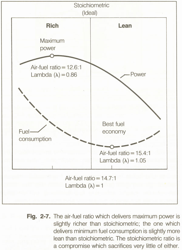
En el siguiente gráfico podemos ver como obtenemos la mayor potencia con una mezcla ligeramente rica (12:1) y como la mayor temperatura de los gases de escape o EGT (Exhaust Gas Temperature) la obtenemos con la mezcla estequiométrica 15:1

¿Por qué se ajusta la mezcla cuando ascendemos?
Cuanto más alto volamos menos denso es el aire y por lo tanto menos masa de aire y oxígeno le entra al motor.
Si nosotros despegamos con la mezcla rica y vamos ascendiendo sin tocar nada, lo que pasará es que cuanto más alto estemos más rica aún estará nuestra mezcla, ya que hemos dicho que al ascender hay menos aire por lo que le estamos metiendo la misma cantidad de combustible pero metemos menos aire, quiere decir que se enriquece la mezcla más aún.
Esto no es bueno, ya que una mezcla excesivamente rica nos quita potencia, enfría en exceso el motor, engrasa las bujías… y además estamos tirando combustible y no está barato precisamente.
Por ese motivo se recorta la mezcla al ascender, para mantener una relación de mezcla adecuada en todo momento.
La mezcla habrá que empobrecerla poco a poco mientras ascendemos.
¿Cómo se enriquece la mezcla al descender?
Estamos volando en crucero, con nuestra mezcla ajustada ligeramente pobre y llegamos al TOD, llega la hora del descenso. Leemos la “Descent” checklist y vemos que pone Mixture……Rich.
En algunas listas pone enriquecer poco a poco.
Evidentemente no tenemos que poner de golpe la mezcla rica, ya que no es lo que necesita el motor, si no que la vamos a ir enriqueciendo poco a poco mientras vamos descendiendo.
Si vuelas un Cessna, una referencia puede ser enriquecer una vuelta (del mando de mezcla) por cada 1.000ft.
De esta manera el motor funcionará siempre con su mejor relación de mezcla, consumiremos menos y alargaremos la vida al motor.
¿Cómo se ajusta la mezcla?
Para el ajuste de mezcla nos vamos a ayudar del indicador de EGT, que nos da la temperatura de salida de los gases.
En ascenso hemos visto que recortaremos poco a poco la mezcla, pero una vez en crucero haremos el ajuste más “fino” de la siguiente manera.
Método 1: Una vez que estemos en crucero con la potencia ajustada y la temperatura del motor estabilizada, vamos empobreciendo la mezcla poco a poco y vemos como va ascendiendo la EGT, hasta alcanzar un pick máximo, para luego descender.
Recordemos que el pick máximo lo alcanza en la relación estequiométrica, en este punto enriqueceremos la mezcla hasta que la EGT disminuya unos 10ºC o 50F.
Método 2: Si nuestro avión no está equipado con un medidor de EGT, lo haremos utilizando el tacómetro del avión.
Vamos recortando mezcla poco a poco y vemos como suben las RPM, cuando lleguen al pico máximo, recortamos un poco más hasta que caigan 25 o 30 rpm.
Al final del post os dejamos un vídeo con este sistema.
Este es un procedimiento genérico estándar, pero el que tienes que seguir es el que indique el manual de vuestra aeronave, ya que cada aeronave y motor tiene sus particularidades.
Por ejemplo el POH de Cessna no recomienda llevar mezcla pobre si llevamos menos de un 75% de potencia en crucero.
Las aeronaves de hoy en día cuentan con sistemas asistidos que nos ayudan al ajuste de la mezcla, logrando un ajuste mucho más fino, como por ejemplo el sistema Garmin G-1000 que cuenta con un asistente para el ajuste de mezcla que es de gran ayuda.
¿Se puede recortar la mezcla en rodaje?
Se puede y se debe.
No se el motivo, pero muchas escuelas enseñan a los alumnos a rodar siempre con la mezcla rica, puede ser que sea por miedo a que se les olvide enriquecer antes de despegar, no lo se, pero para esos están las listas de chequeo.
En rodaje necesitamos una potencia mínima, si tenemos la mezcla rica estaremos desperdiciando combustible y lo que es peor, estaremos engrasando las bujías y luego en la prueba de magnetos puede que tengamos que hacer una limpieza o a la larga cambiarlas antes de tiempo.
Por ello es recomendable siempre ajustar la mezcla también en rodaje.
El procedimiento que recomienda Cessna es el siguiente: Una vez arrancado el motor, encendidas las radios, sistemas etc, ponemos el motor a 1.200 rpm, ahora vamos recortando la mezcla poco a poco hasta que suban 50 revoluciones, es decir hasta tener 1.250 rpm.
Recuerda, recortar la mezcla en rodaje es bueno para el motor, el medio ambiente y para el bolsillo.
Hace unos días leí un artículo en AOPA que hablaban de otro procedimiento que llamaban algo así como “recorte de mezcla extrema” y es precisamente para lo que indicábamos antes, recortar la mezcla pero evitar que se pueda olvidar enriquecerla antes de despegar.
La técnica en este caso era recortar mucho en rodaje, de esta manera al hacer la prueba de motor y meter gases, el motor ratearía y nos daríamos cuenta de que estaba empobrecida.
Personalmente prefiero el procedimiento de Cessna, pero como hemos dicho, consultad primero el POH de vuestra aeronave.
¿Hay que despegar siempre con la mezcla rica?
No. En muchas listas “Before takeoff” pone Mixture……Rich ya que lo normal es que no volemos en campos con gran elevación y en ese caso despegamos con mezcla rica.
En otras listas colocas Mixture…..Best power. Es decir, si estamos despegando de un campo que está a 8.000ft y ponemos la mezcla rica, vamos a perder mucha potencia o incluso podemos tener problemas con el motor ya que le estamos introduciendo demasiado combustible para el poco oxígeno que entra.
O si tenemos una temperatura muy elevada, es decir lo que nos va a afectar es la altitud de densidad que tengamos.
Como decimos, no es muy común volar en campos con tanta elevación, pero hay que tenerlo presente por si algún día se nos presenta la ocasión.
¿Siempre se recorta a partir de 5.000ft?
No. Como hemos dicho incluso puede que tengamos que ajustar la mezcla para el despegue.
Se suele decir que a partir de 5.000 ft se recorta la mezcla, porque es una altitud a partir de la cual el motor ya tendría una mezcla bastante rica, lo que nos perjudicaría tanto en la potencia entregada como en su correcto funcionamiento, pero la mezcla la podemos ir empobreciendo poco desde que empezamos a ascender y una vez en crucero haremos el ajuste más fino.
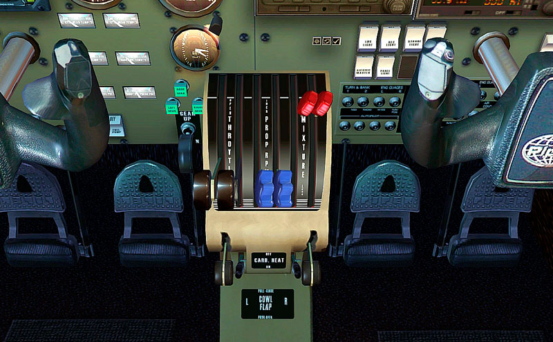
¿Cómo se presenta el mando de mezcla?
Dependiendo del fabricante tendremos un sistema de mandos de motor u otro, pero la función es la misma.
El mando de mezcla suele ser de color rojo y estar a la derecha del todo.
Si el avión es bimotor tendremos un mando de mezcla para cada motor.
Tenemos el diseño de Cessna, en el que los controles de mando se deslizan introduciéndose más o menos. Para un ajuste más preciso de la mezcla, podemos girar el mando. Sentido horario se enriquece la mezcla y sentido anti horario se empobrece.

El sistema elegido por Piper es diferente en su presentación, pero la función es la misma.
Si empujamos la palanca enriquecemos la mezcla y si retrasamos la palanca empobrecemos.
sábado, 26 de noviembre de 2016

jueves, 24 de noviembre de 2016
martes, 22 de noviembre de 2016
Aproximaciones RNAV (GNSS) en SCSN
Lento aún.... pero vamos avanzando finalmente hacia una nueva etapa de instrucción IFR, con las publicación de las aproximaciones RNAV (GNSS) de SCSN, en próxima actualización del AIP CHILE VOL II, del mes de Diciembre


Aporte Piloto Diego Jara
domingo, 20 de noviembre de 2016
viernes, 18 de noviembre de 2016
jueves, 17 de noviembre de 2016
miércoles, 16 de noviembre de 2016
El error en Aviación.
"Por cierto que en la aviación, el errar es humano, pero aún así es bueno reconocer cuando te haz equivocado antes de que otros lo exageren más de la cuenta".
JMDF
martes, 15 de noviembre de 2016
VDPs
Visual Descent Points
VDP: “A defined point on the final approach course of a non-precision, straight-in approach procedure from which normal descent from the MDA to the runway touchdown point may be commenced, provided the approach threshold of that runway, or approach lights, or other markings identifiable with the approach end of that runway are clearly visible to the pilot.”
A normal descent from the MDA to the runway touchdown point is key to the definition of a VDP above. During a straight-in, non-precision approach the VDP will be located prior to the Missed Approach Point if one is in fact published. The reality is that if a pilot reaches the missed approach point he may not be in a position to land when he sees the airport. This is especially true for higher performance aircraft like jets and turbo props, but this does not exclude slower general aviation aircraft. A pilot attempting to dive at the runway can destabilize the approach, especially at night with low visibility, and non-stabilized approaches are a leading cause of accidents. The Visual Descent Point allows for a 3 degree descent to the runway, and thus a stabilized approach.
Making Your Own VDP
What happens when there is no VDP published? It is simple to create your own, and this is something that is routinely used by professional pilots for these types of non-precision approaches.
First, figure out the height above terrain (HAT) of the MDA. Now, divide the HAT by 300. The number you get is the distance from the runway threshold (in nautical miles) of your visual descent point. In mathematese: VDP = HAT / 300
Let’s take an example. Consider the localizer approach to runway 2R in Nashville where the HAT at the MDA is 550 feet. To make the mental math easy (aren’t we busy enough up there?) let’s round it up to 600 feet. Recall that VDP = HAT / 300, so we have to compute: 600 / 300 = 2
The VDP for this approach is 2 miles from the runway threshold. But wait, there’s more. How will you know when you are precisely 2 miles from the threshold? Notice that the runway threshold is at a DME of 1.5 from the localizer. Just add 1.5 + 2 to get our DME reading of 3.5 at the visual descent point.
Although most newer aircraft have advanced avionics packages with GPS glideslopes, many of us still have to fly the old “dive and drive” type straight-in, non-precision approaches from time to time. If so, learn how to quickly compute these VDPs, and fly safer, more stabilized approaches.
lunes, 14 de noviembre de 2016
Horizontal Situation Indicator

Contents
[hide]General Description
HSI is the acronym for Horizontal Situation Indicator. Sometimes it is also called Pictorial Navigation Indicator. It combines a standard Directional Gyro (DG) and Course Deviation Indicator (CDI) into one single instrument and reduces the pilots workload by displaying the aircraft's heading and position relative to a desired course in a compact manner.
The well known drift of a standard Directional Gyro is usually compensated by the use of a slaved gyro system that constantly corrects the heading indication.
The purpose of this document is to briefly describe the indicators and the usage of a HSI instrument.

Indicators
Compass Card / Compass Rose
The Compass Card (1) is driven by the internal gyro. It shows the magnetic heading of the aircraft. Drift errors like in standard Directional Gyro are automatically corrected when in slaved mode.
Lubber Line
The number on the Compass Card (1) under the Lubber Line (2) shows the current aircraft magnetic heading.
NAV Warning Flag
The red NAV Warning Flag (3) indicates, that either CDI or the GS indicators are unreliable. It is driven by the signal quality of the received nav station. Do not use the CDI or GS indicators for navigation when the NAV Warning Flag is visible.
HDG Warning Flag
The red HDG Warning Flag (4) becomes visible when the speed of the directional gyro is to low. Beware that there may occur compass failures that are not indicated by the HDG Warning Flag, so compare the indicated heading with the magnetic compass on a regular basis. If the HSI is part of a slaved gyro system, the HDG Warning Flag also appears if the gyro has lost synchronization with the master. On a KCS55 this will happen, if a offset of more than 3 degrees is detected between earth magnetic field and the gyro indication. It also shows up, if the slaved gyro system is switch to manual mode.
Heading Select Bug
The orange Heading Select Bug (5) indicates the heading you (the pilot) wants to fly. It may be coupled to the autopilot so can provide the "Heading Select" function. The autopilot will try to maintain the heading indicated by the Heading Select Bug. The Heading Bug can be adjusted by the Heading Select Knob (11)
Course Deviation Bar
Like a standard Course Deviation Indicator (CDI) the Course Deviation Bar (6) shows how far the aircraft is off the selected course. When the bar is in line with the yellow arrow head and tail the aircraft is exactly on the selected course. When the bar moves to the right when looking in the direction of the arrow, the desired course is on the right (with respect to the aircraft's heading). The scale under the bar shows how far off course the aircraft is. In VOR navigation, each dot corresponds to a deviation of two degrees, allowing a total of +/- 10 degrees. During the reception of a LOC signal each dot on the CDI scale corresponds to a deviation of 0.5 degrees, a full deflection is 2.5 degrees off course. The advantage to a standard CDI is, that the entire indicator rotates with the Compass Card, giving the pilot a pictorial symbolic view of the relationship of the aircraft's heading, the selected course and the current position.
Course Select Pointer / Cursor
The Course Select Pointer (7), often simply called Cursor, is set by the pilot using the Course Select Knob (10) to the desired VOR or LOC course which is shown under the head of the arrow while the tail marks the reciprocal course.
To/From Indicator
Two white triangles (8) near the center of the display indicate, whether the selected course is to or from the tuned VOR. They correspond to the "To" and "From" flag of a standard CDI display. There is either only the "To" or only the "From" or no flag at all in the view. One will never see both flags like in the descriptive image on the right.
Glideslope Pointer
The Glideslope Pointer (9) come into view when a glideslope signal is being received during a ILS approach and the aircraft's position is within the defined range and slope of the glideslope signal. This is a very sensitive display. A full deflection correspons to a 1.4 degrees difference in the glideslope. A one dot indication showing a deviation of only 0.35 degrees off the glide slope.
Course Select Knob
Use the Course Select Knob (10) to turn the Course Select Pointer (7) to match the desired course on the Compass Card (1). This knob has the same function as the OBS knob on a standard CDI.
Heading Select Knob
The Heading Select Knob (11) moves the Heading Bug (5) to the desired heading on the Compass Card (1)
domingo, 13 de noviembre de 2016
How a VOR Works
16 Feb, 2014 in Articles / IFR Flight
VOR is short for Very High Frequency (VHF) Omni-directional Range. When VOR was invented it replaced the Low-Frequency Range, which had only four legs. Thus the term “Omni-directional”, indicates that a VOR generates courses in all directions, which is its distinctive characteristic.
VOR is also distinct from Non-directional Beacons (NDB) in that the directional signal is embedded in the VOR signal. With an NDB there is no directional information embedded in the signal thus the airborne radio must have direction finding abilities.
I have created a computer animation, shown below, that explains in pictures better than I can do it in words how a VOR station works.
Basically the VOR transmits two signals. The “phased signal” is transmitted outward in a spiral, shown in blue in the animation. A second signal is transmitted simultaneously with each revolution of the spiral. This second signal acts as a timing reference. Your VOR receiver picks up both signals and acts like an oscilloscope creating a standing wave of both signals. The phase difference between the signals represents the radial you are on. A radial is simply your bearing awayt from the VOR.
In the animation I have slowed the process down so that you can see it. In a real VOR the signals are transmitted 30 times per second and move out at the speed of light.
For more details of how VOR works here is an article on Wikipedia.
In the animation you can drag the airplane around the VOR to all the different radial. As you do so watch the standing waves at the bottom. You will notice that the phase difference between the red and blue waves corresponds to the radial you are on.
Radials are Relative to Magnetic North
A radial is by definition a direction, or course, outward or away from the station.
When a VOR station is installed it must be calibrated. In most parts of the world VORs are calibrated so that the zero radial is oriented toward Magnetic North. In the simulation above the VOR is initially oriented to True North, but you can adjust the variation slider in the animation and you will see that it reorients the VOR to Magnetic North. All the calibration actually does is change the starting point of the timing pulses (the red pulses) so that a new one starts as the spiral passes Magnetic North.
In northern Canada VORs are oriented to True North.
Now that we know how a VOR station works and how our radio interprets the information let’s examine how the course is displayed to the pilot in the cockpit
Display of VOR Course in the Cockpit
Three different instruments are in common use for displaying VOR information to pilots in the cockpit. In order from oldest to most modern they are:
- RMI
- Standard VOR Indicator
- HSI
I will explain each in order.
There is a simulation below that you can use to explore and compare how these three indicator systems work. You can drag the airplane around to see how the RMI, Standard VOR Indicator and HSI react. You can change the course using the OBS and CRS knobs (just hold the mouse button down on the knob.) You can also turn the airplane by adjusting the heading bug.
Use the “Sectors” button to see how an HSI or Standard VOR Indicator dissect the world into 8 unique sectors.
Radio Magnetic Indicator (RMI)
The oldest method of displaying VOR information is called an RMI, short for Radio Magnetic Indicator. An RMI is simply a rotating needle on top of a heading indicator.
In the animation below the blue needle is the RMI-needle. I have chosen to install the RMI-needle as part of an HSI (I will describe HSI in a moment.) It is common practice these days to install the RMI-needle as part of an HSI rather than as a stand-alone instrument. But, some airplanes with older avionics have the RMI as a separate instrument. Either way it works the same.
In the animation drag the airplane around and notice how the blue RMI-needle reacts.
Most pilots would say that the RMI-needle is pointing at the VOR. In reality it is rotating so that the tail of the RMI-needle indicates which radial you are on. The difference between these two points of view is rather subtle. As long as the heading card is accurately indicating your heading there is no difference. But should the heading system fail the RMI-needle no longer points at the station, but the tail of the needle would still tell you what radial you are on. I will write an article about failure modes at a later time.
Standard VOR Indicator
RMI has the advantage of being simple, both to construct and interpret, but it requires a lot of skill to navigate accurately with it. Consequently, soon after VOR was invented the Standard VOR Indicator was invented.
The Standard VOR Indicator is still in use today, although low-cost HSIs are rapidly replacing it.
The Standard VOR indicator lacks the ease of use of the RMI, but once setup a pilot can fly very precisely along a straight course. The ability to fly a straight line accurately is the only advantage.
The Standard VOR indicator lacks the ease of use of the RMI, but once setup a pilot can fly very precisely along a straight course. The ability to fly a straight line accurately is the only advantage.
The pilot uses a knob, known as the Omni Bearing Selector or OBS to choose a radial to navigate along. Once the pilot has made the choice all that is necessary is to keep the Course Deviation Indicator (CDI) centered in order to fly a perfectly straight course along the radial or the reciprocal of the radial.
The Standard VOR Indicator also has a TO/FROM flag. The flag indicates FROM whenever the airplane is within 90 degrees of the chosen radial, and therefore indicates TO whenever the airplane is more than 90 degrees from the chosen radial.
The CDI will deflect left whenever the airplane is clockwise up to 180 degrees from the chosen radial and will deflect right whenever the airplane is up to 180 degrees counter-clockwise from the chosen radial.
The CDI is “alive” whenever the airplane is within 10 degrees of the radial or its reciprocal. If the CDI is centered with a FROM flag that means the airplane is on the selected radial, but if the CDI is centered with a TO flag (remember the TO flag shows when the airplane is more than 90 degrees from the radial) that means the airplane is 180 degrees off the radial, i.e. on the reciprocal of the selected radial.
When the airplane is abeam the station (approximately 90 degrees, either clockwise or counter-clockwise from the station) an OFF flag replaces the TO/FROM flag.
In the animation above you can drag the airplane around to see how the Standard VOR Indicator shows your position.
You can see from the simulation that there are 8 unique combinations of CDI and TO/FROM flag. To fully understand and use a VOR you need to understand each of the 8 possibilities.
If you can find an experienced IFR instructor to sit down with you as you explore this animation that would speed up your understanding.
Horizontal Situation Indicator (HSI)
The Horizontal Situation Indicator, or HSI, is a much easier instrument to use than the Standard VOR Indicator.
The HSI has all the same components as the Standard VOR Indicator. It has a Course Knob, which has the same function as the OBS knob on the Standard Indicator. It has a CDI and a TO/FROM flag. The extra thing it has is a Track-Bar (also known as a Course-Bar) that rotates with the heading card.

In the animation above you can set the HSI to any course you like. Notice that the Track-Bar rotates as you change the course. You can also make a turn by changing the heading bug using the HDG knob. When the airplane turns the Track-Bar turns and that is the innovation that makes it so much easier to visualize where your desired course is relative to your airplane.
Many pilot believe that when the CDI is deflected left they need to turn left and when the CDI is deflected right they need to turn right. With an HSI that is true, but with a Standard VOR Indicator it is not necessarily true. I will explain this point in an upcoming movie. This difference is the reason why the HSI really does give you situational awareness, hence the name. It is always safe to say that you should turn toward the CDI with an HSI, but with a Standard Indicator that is not always the case.
After many decades of training IFR pilots have have noticed that many pilots using HSI for the first time do not discriminate the TO/FROM flag very well. On the HSI the TO/FROM flag is a small triangle which points toward the arrowhead to indicate TO or toward the tail of the Track-bar to indicate FROM. Compared to the flag on the Standard Indicator it is quite subtle and many pilots fail to notice when the flag “flips” so watch out for that.
As with the standard indicator your best bet is to sit down with an experienced IFR instructor when exploring the animation above and do a side-by-side comparison of the standard indicator and the HSI.
viernes, 11 de noviembre de 2016
How Do You Fly an LPV Approach?
Helpful tips and detailed explanations from a pro.
By Max Trescott May 4, 2012

By Max Trescott May 4, 2012
LPV Approach
One challenge for instrument pilots is that the rapid change in technology found elsewhere in our lives has invaded the cockpit. In the past, pilots had it easy when flying an ILS (instrument landing system) approach. By dialing in the right frequency and keeping the needles centered, a pilot could successfully fly an approach even using radios he or she had never seen before.
GPS changed everything. If you know how to operate a particular GPS model and can successfully load a GPS approach, flying an approach to LPV minimums can be as simple as flying an ILS approach. Of course each GPS is different and the odds of successfully loading an approach on an unfamiliar GPS are slim. So flying a GPS approach to LPV minimums can be as simple as flying an ILS approach, but only if you’re extremely familiar with the GPS in your cockpit.
That said, flying a GPS approach can be so complicated you could write a book about it. So I did; much of what you’ll read here comes from my Max Trescott's GPS and WAAS Instrument Flying Handbook.
Technically there is no such thing as an “LPV approach.” Instead, LPV is just one of several minimum types that can be flown on a GPS approach with a WAAS-capable, instrument-certified GPS. LPV stands for “localizer performance with vertical guidance,” meaning it’s similar in precision to the localizer and glideslope of an ILS approach.
LPV minimums, usually 200 or 250 feet agl, are typically the lowest available on a GPS approach. Other minimum choices may include LNAV/VNAV, LP, LNAV and circling. You can usually ignore the LNAV/VNAV minimums, since LPV minimums are almost always lower. LP, or localizer performance, minimums are like a localizer approach; the angular guidance narrows as you near the runway and there’s no vertical guidance.
LNAV, or lateral navigation, mini-mums are used to fly a series of stair steps until you reach a minimum descent altitude (MDA). They are the only straight-in GPS minimums that can be flown with a non-WAAS, approach-certified GPS. Circling minimums permit you to circle to land on any runway, except those prohibited in the chart notes.
Flying an approach to LPV minimums starts long before you reach the approach. Your preparation before leaving the ground should include checking that your GPS database and charts are current — and if your charts are on an iPad, checking that the iPad is fully charged. You’ll also want to contact Flight Service for any WAAS notams. If flying in oceanic or remote areas, the FAA requires that you run an FDE prediction program, available from Garmin and other companies, to check GPS satellite coverage.
En route, you can check RAIM if you’re planning to fly to LNAV minimums. But RAIM can’t tell you if you’ll have sufficient signal quality to fly to LPV minimums, so there’s no need to check it if you plan to fly to LPV or LNAV/VNAV minimums. Incidentally, if you do a RAIM check and it fails, you may want to play the lottery.
The current GPS availability for nonprecision approaches in the continental United States is more than 99.99 percent, meaning on average, if you check RAIM 10,000 times, you’ll fail to get RAIM only once!
But don’t be surprised if there’s insufficient signal quality to fly to LPV minimums. Along the East and West Coasts of the contiguous 48 states, availability can be as low as 99 percent, meaning that for one out of every 100 attempts, you won’t be able to fly to LPV minimums. But the good news is those outages are very short, usually no more than 15 seconds. So, if you do arrive during one of those outages, you may want to get vectored around to try the approach again. In Alaska, signal availability to fly to LPV minimums is significantly lower.
En route, brief the approach by reviewing the chart. Verify that GPS is in the title of the approach and not RNP (required navigation performance), because those approaches cannot be flown with a WAAS-capable GPS. Then set all frequencies including the one for weather at your destination.
Before loading the approach in the GPS, determine whether you’ll fly the approach using vectors, during which the controller issues a series of turns onto the approach, or via pilot navigation, where you fly the approach from a starting point without guidance from the controller.
Note that with some GPSs, loading an approach with vectors deletes all but the last few waypoints on the approach. In the flatlands that won’t matter, but in hill country I recommend that you not load an approach with vectors, even when being vectored onto the approach. Instead, load the approach with an initial approach fix (IAF) that produces a straight-in approach without a course reversal. Then activate the leg of the approach the controller is vectoring you toward.
One common mistake I see is failure to check and set the “kill switch.” That is the switch that determines whether the CDI or HSI course needle is displaying course guidance from a VOR receiver or a GPS. Leave it in the VOR position when flying a GPS approach and you could get killed.
Once you’ve properly set up your equipment, flying to LPV minimums is like flying an ILS. As you intercept the glidepath, reduce power and slightly lower the nose to descend. Keep the needles centered as you would for an ILS, and when you reach the decision altitude listed on your chart for LPV minimums, decide whether to land or to fly the missed approach. Don’t continue flying level at minimums while looking for the airport. If you don’t see the airport upon reaching LPV minimums, you must immediately initiate a climb.
Before flying an approach to LPV minimums in poor weather, practice doing it in clear skies. After all, the life you save may be your own!
_
Max Trescott is the 2008 National Certificated Flight Instructor of the Year. Based in Palo Alto, California, he publishes aviation books and software, including Max Trescott's GPS and WAAS Instrument Flying Handbook and Max Trescott's G1000 Glass Cockpit Handbook. He teaches in Cirrus and other glass cockpit airplanes and in Lake amphibians. You can learn more about Max at g1000book.com.
and Max Trescott's G1000 Glass Cockpit Handbook. He teaches in Cirrus and other glass cockpit airplanes and in Lake amphibians. You can learn more about Max at g1000book.com.jueves, 10 de noviembre de 2016
Jornada de Estandarización IV
Jornada de Estandarización e Información destinada a instructores de vuelo de aviones y helicópteros, de Empresas Aéreas de aeronaves pequeñas y de Aviación General.
Ubicación
- Fecha y Horario de Inicio:
- Fecha y Horario de Término:
miércoles, 9 de noviembre de 2016
martes, 8 de noviembre de 2016

lunes, 7 de noviembre de 2016
domingo, 6 de noviembre de 2016
sábado, 5 de noviembre de 2016
TEACHING IFR
Approach plates can be deceptive
Most instrument-rated pilots--and I'll bet a few instructors--have no idea that the missed approach point (MAP) shown on some approach charts can be distressingly far away from the real missed approach point. Further, the visibility requirements noted in the minima section may be wildly optimistic, as demonstrated the other day by one of my IFR students. "Whoa!" I exclaimed as my student began a sudden descent to the runway following a nonprecision approach to minimums. We were simulating a GPS approach where the MAP was at the runway end. I let him fly to within one-half mile of the approach end before raising his hood and waiting for what would happen next. As expected, the power came to idle, the flaps deployed, and the airplane pitched sharply downward as he attempted to land on the rapidly diminishing length of concrete below. After a go-around and landing, we retired to the classroom to chew on this.
Let's look at what is required to descend below MDA. According to FAR 91.175, we must have:
The required flight visibility;
At least one item associated with the runway environment, as defined in FAR 91.175(c)(3); and
A position from which we can make a normal descent and landing
It is this last one that causes the problem. Not every instrument instructor teaches his or her students how to calculate the required descent and the need to establish a practical MAP based on the realities of the approach to be flown, rather than just blindly accepting the published MAP location on the chart. Both VFR and IFR pilots are guilty of not figuring out when they need to begin descent in order to avoid arriving in the terminal area too high and too fast. The problem is exacerbated by the fact that many high-performance airplanes will not easily go down and slow down simultaneously.
But when it comes to the most critical part of the approach, many IFR pilots just accept the location of the MAP as shown on the approach chart, especially when it is at the approach end of the runway. The pilot arrives at the minimum descent altitude (MDA), levels off, and begins to search for the airport. In low visibility, the runway often appears suddenly out of the murk and the pilot tries to descend and land without realizing he or she is too high to complete the landing without some sort of dramatic maneuver involving lots of flaps, chopping of power, pushing over the nose, and increasing speed. None of this is in keeping with the idea of a stabilized approach, and such antics certainly don't meet the "normal descent and landing" requirements of FAR 91.175. Resulting difficulties include hurried descents, rushed decisions, runway overruns, and missed approaches.
My student really never had a plan for the vertical part of the approach procedure, and I'll bet that the majority of other pilots don't, either. Shouldn't we be teaching that the MAP isn't always practical as printed, and that the visibility requirements may be just a wishful dream? This problem can exist on any nonprecision approach, but especially when the MAP is at the runway end. Factors to consider include the altitude between the final approach fix (FAF) and the MDA; the descent required to reach the runway; and the visibility, wind, and ceiling. In many GA aircraft, pilots fly approaches at 120 knots, which is two miles per minute. With a descent rate of 500 feet per minute, they lose approximately 250 feet per mile. If the approach requires a descent of 500 feet from the MDA to the runway, the pilot must see the landing environment at around two miles out to have any hope of completing the approach safely. Therefore, the practical MAP is two miles from the threshold, not at the runway end. This also means you need at least two miles of visibility to land, regardless of what the approach minimums call for.
The FAA is slowly improving many of the instrument approach procedures by specifying a visual descent point (VDP) at which the pilot should expect to see the runway and continue along a 3-degree glideslope to the threshold. (This point is marked with a bold "V" on the profile view on Jeppesen charts, and it must be observed if you have the capability of identifying the VDP.) By noting the distance remaining at the VDP, you can establish a realistic minimum visibility that should result in a safe and stable approach.
For a pilot making 120 knots on final, it's easy to figure out the real MAP by dividing the required altitude loss from the MDA to the touchdown zone by 300. The result is the distance in miles that you need to see the runway. This value may be somewhat conservative, but even if you adjust it for your particular rate of descent in feet per mile, it will still give you a way to avoid an ugly surprise and possible dangerous attempt to salvage a blown approach.
Ken Wittekiend, a CFII, co-owns Eagle Training Solutions in Burnet, Texas. He owns a Beech Bonanza and a Piper Super Cub, and with more than 8,100 hours in his logbook is still enthusiastically instructing full-time. He specializes in advanced IFR training and tailwheel proficiency.
CFI Roundtable slated for Expo
If you plan to attend AOPA Expo 2007 in Hartford, Connecticut, this October, please join us for AOPA Flight Training's annual CFI Roundtable. The meeting will be held Saturday, October 6, from 11 a.m. to noon in the Capital 1 room of the Marriott Hartford, which adjoins the convention center. Topics of discussion will include the sport pilot certificate, technically advanced aircraft, and AOPA's Project Pilot. For more information, e-mail Mike Collins.
Suscribirse a:
Entradas (Atom)